

Foreword: This month’s Spotlight article is written by our resident programmer/electrical engineer/web-designer/brewer, Alex Long. Alex has been with Build Equinox since 2009, developing the internal controls systems, sensor integration, user interfaces, and online functionality of the CERV and CERV2. This article highlights Alex’s recent attempt to merge the CERV and an antique 1940/1950s General Electric refrigerator into a high efficiency, smart Kegerator (i.e. beer-serving refrigerator). And as a bonus at the end, check out his newest brew using hops from Build Equinox!
From CERV to CERVEZA: A Quest for Smart Beer
By Alex Long
Part 1: Background
I always looked for an excuse to have a Kegerator. For those of you who aren’t familiar, a Kegerator is a refrigerator modified with added faucets on the front (or sometimes, top). It basically allows you to serve delicious, fresh, cold beer without the risk of chipping a fingernail on a pull-tab or arduously hunting down a bottle opener. Additionally, since I am a frequent homebrewer, the idea of simply filling a 5-gallon keg with a batch of beer instead of cleaning, sanitizing, filling, and capping 50 bottles is very, very attractive.
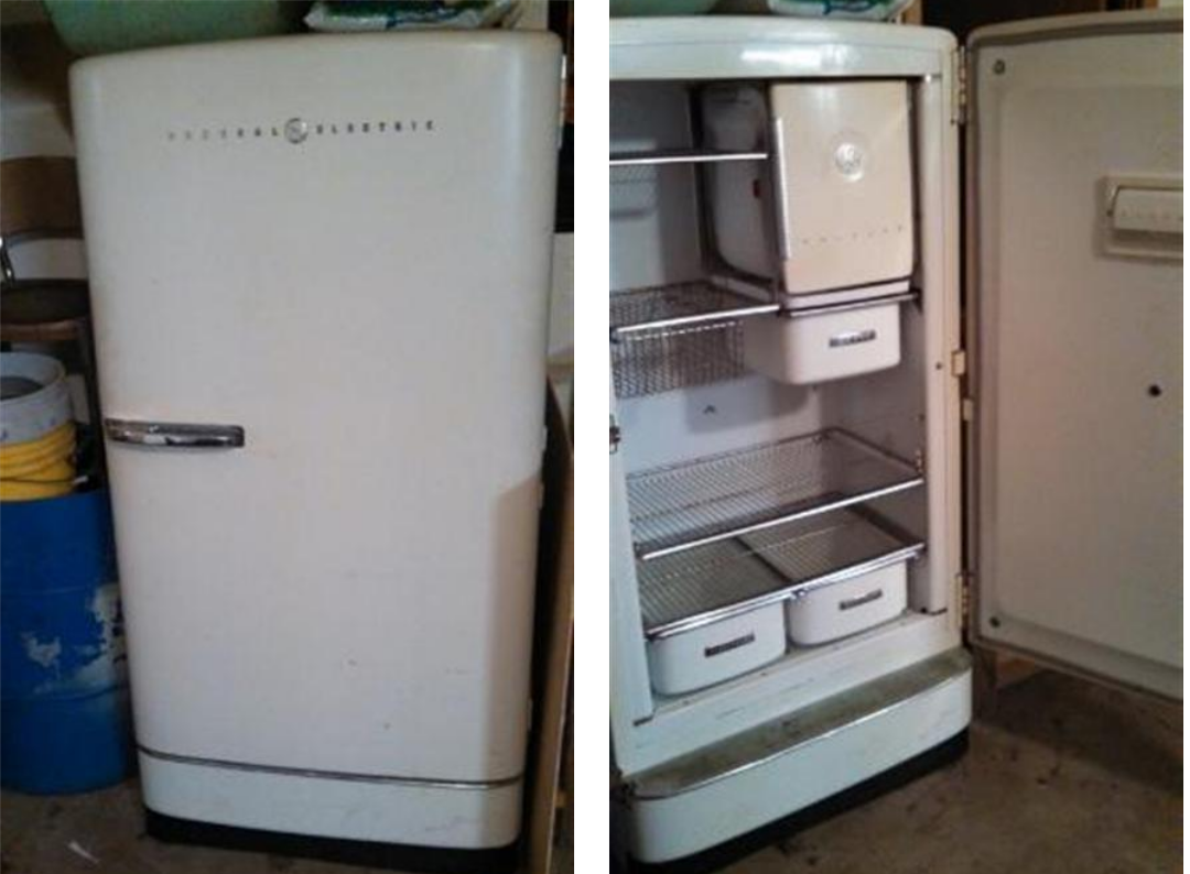
Lucky for me, I found the perfect excuse. Back in 2013, as my wife and I were planning our upcoming wedding, we had the idea to serve homebrew to friends and family at the rehearsal dinner. I then lucked out even further and found a 1940/1950s era General Electric refrigerator on Craigslist, still functioning, only a short drive away, and only $100!
Over the next month, I disassembled the refrigerator, sanded, painted, re-sanded and re-painted, drilled holes, and installed the hardware to turn it into a fully-functioning vintage Kegerator! If you’re interested in that whole process, check out the link below to the full album.
 Go here to view the album
 I’m not saying that Martha Stewart got the idea from us for this recent Instagram post, but I’m also not not saying that…
Part 2: Present Day (disaster strikes)
My wife, the Kegerator, and I enjoyed six blissful years together, until one night the refrigeration system couldn’t take it anymore. It was tired of being used, and feeling burnt out. It just couldn’t keep its cool, so it wanted out. In other words, it died and I was going to have to drink warm beer until I could figure out what to do.
Option 1: Try to find the refrigerant leak in the piping, patch it, and recharge with new refrigerant. The system is so old, though, that I would likely just have to keep patching leaks over and over again. The other issue is the refrigerant used in these old systems is R-12, and you simply cannot buy it anymore. The closest you can get is a blend of Propane/Butane, but the idea of filling an ancient leaky refrigerator with explosive gasses is a little bit unsettling.
Option 2: Tear out all the old components and start over with a new heat pump system. Put together a few components, use an off-the-shelf temperature controller, and call it a day. An easy path to cold beer.
Option 3: Similar to option 2, but instead go way overboard. Refrigeration components? I could take apart an old first generation CERV and use its high efficiency, speed controllable compressor along with the heat exchangers and electronically controlled expansion valve. Custom enclosure for components? Better use my 3d printer. Temperature control? I should probably have a touchscreen interface that allows me to not only set the fridge temperature, but also view the power consumption, measure the delivery temperatures to tune heat pump performance, and fully configure each electronic component. Oh, and it should also probably have a web-server, so I can monitor it remotely from my phone.
Clearly, the correct option is to over-engineer the heck out of it and spend months of already scarce free-time building a smart Kegerator.
Part 3: The C in CERV
The C in CERV stands for Conditioning, and it’s one of the things that sets the CERV apart from most other Energy Recovery Ventilators on the market. The highly efficient heat pump inside the CERV allows the system to effectively exchange energy between incoming fresh air and outgoing stale air while ventilating your home. If you’re new to the CERV or ERV/HRV systems in general, check out our recent free webinars on YouTube.
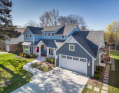
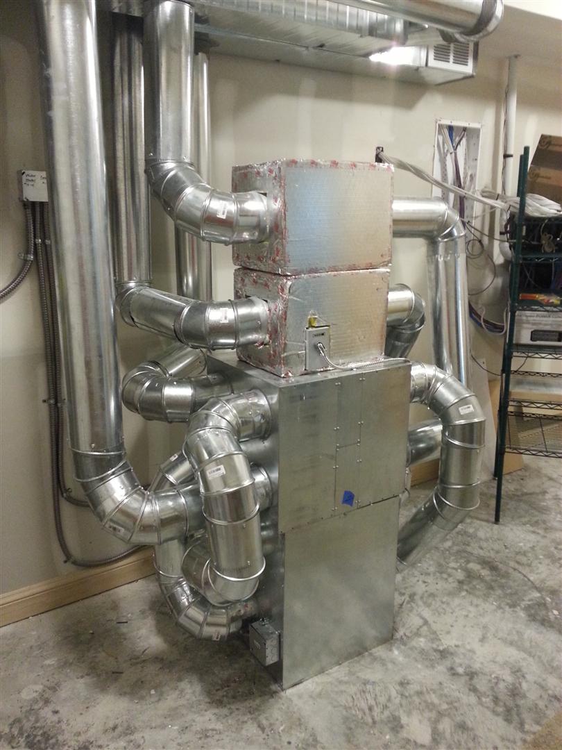 The very first first-generation CERV in its natural basement habitat. The bottom module contains the heat pump system.
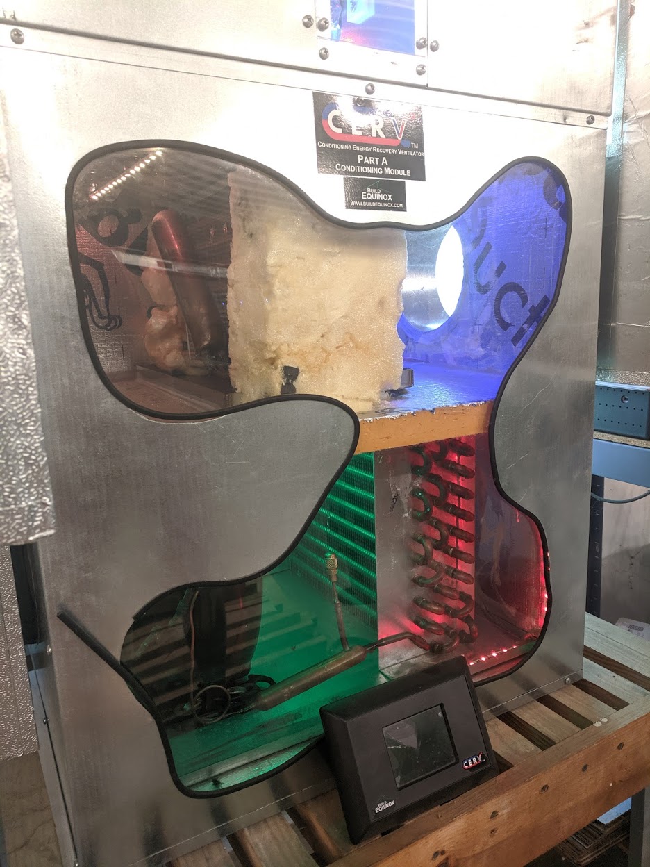 First Generation CERV “Show Unit”. Top half of the module contains the Evaporator, which cools and dehumidifies (blue). The bottom half contains the Compressor and Condenser, which heats the air (red).
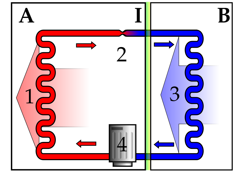
A quick refresher on the Refrigeration Cycle:
1) Air is heated by passing over the Condenser (heat added to the air in A)
2) The refrigerant leaving the Condenser is dropped in pressure, causing a similar drop in temperature.
3) Air is cooled by passing over the Evaporator (head removed from the air in B)
4) The refrigerant increases in pressure and temperature by passing through the Compressor
In the CERV’s case, A and B of the above diagram are the incoming and outgoing air streams. In a refrigerator, A would be where you live, and B would be where the beer lives. Same basic concept.
In our store room, we had a couple of prototype heat pump systems from the very first production of CERVs, so instead of getting sold as scrap metal I figured I could bring it new life as a very efficient beer delivery device. Also, I am known for being very cheap and this was very free.
Part 4: Disassembly
When people say “they don’t make things like they used to”, they are specifically referring to this refrigerator. You are able to remove the ENTIRE compressor/condenser/evaporator assembly from the back of the refrigerator by taking out about 10 screws, and then sliding out (see the picture below). You’re on your own after that, though, because it’s about 100lbs of awkwardly distributed steel.
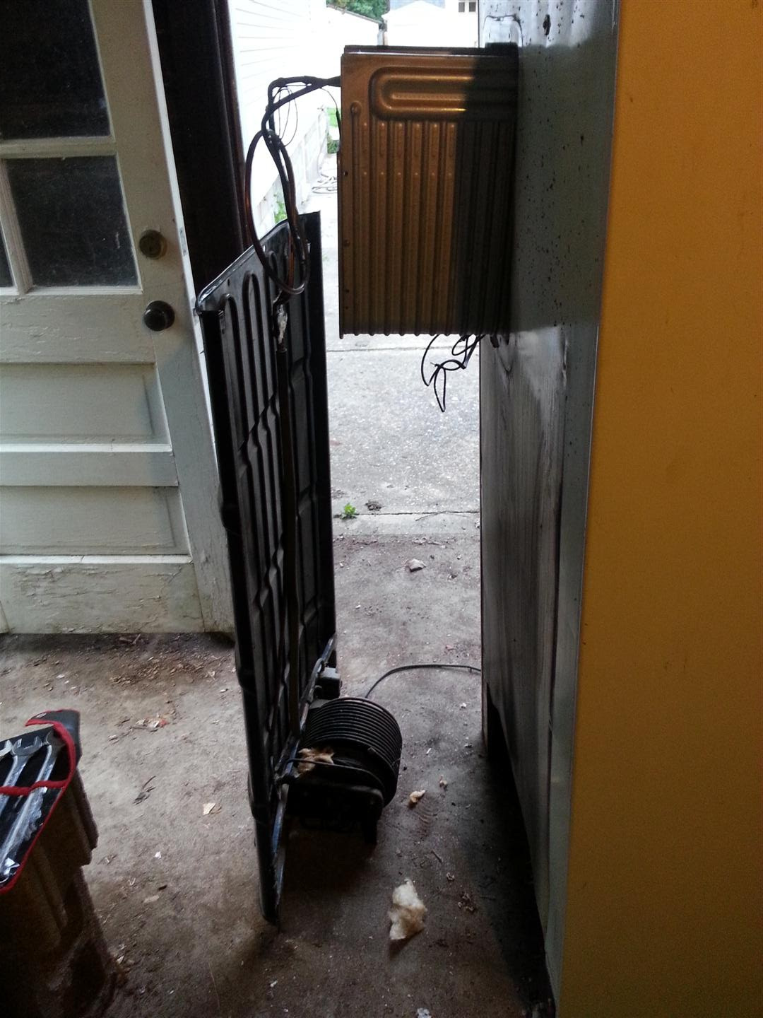 Disassembly Instructions - Step 1: disassemble.
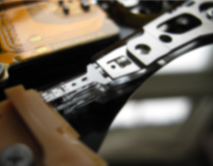
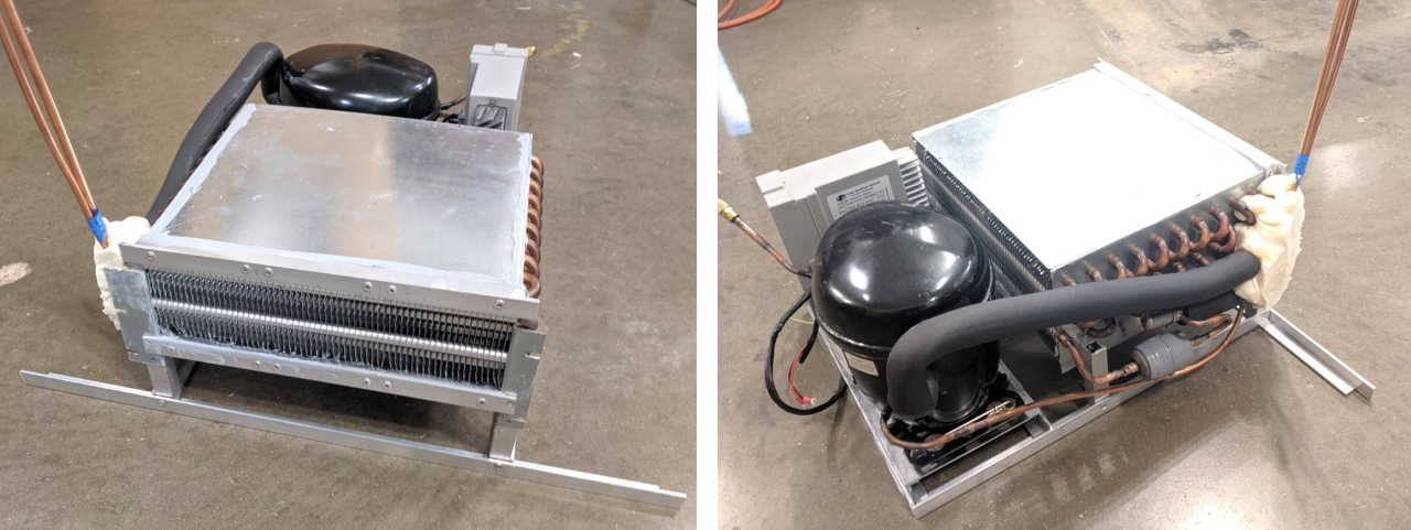
For recovering the heat pump from the CERV test unit, I had to get a bit more destructive. We try to use as much recyclable material in the construction of our systems, so the sheet metal enclosure of the unit could be scrapped for a little bit of lunch money. After stripping it down to the essential heat pump components, all the refrigerant was recovered (it’s illegal to knowingly release refrigerant into the atmosphere). You can see what the bare heat pump looks like below.
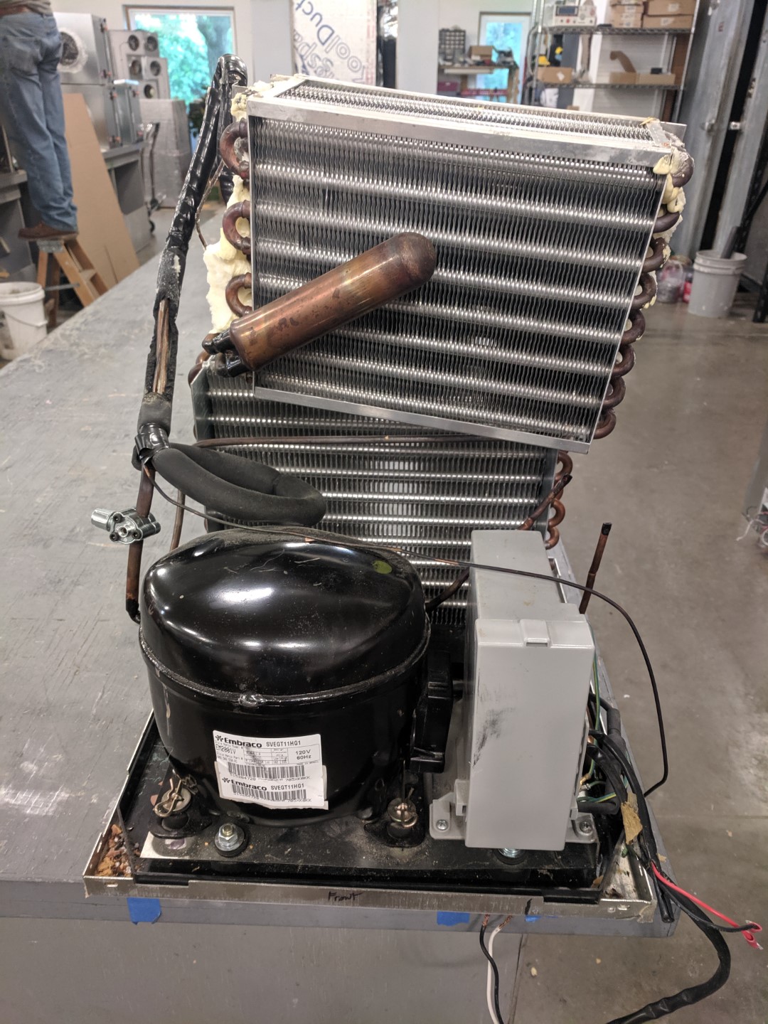 After isolating the heat pump and removing refrigerant, it was then cut into individual components.
Part 5: The Design & Construction
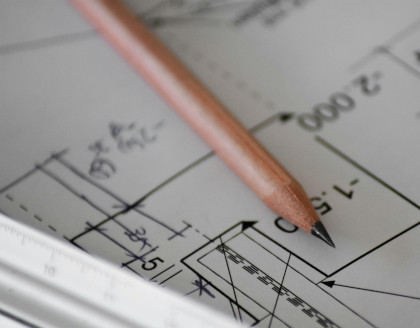
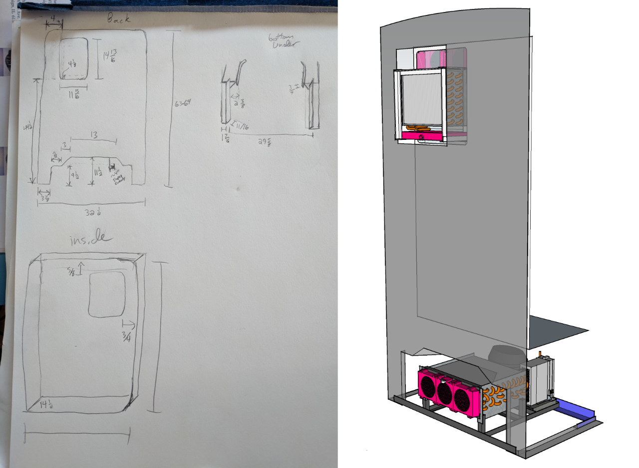 Left: Very precise measurements. Right: I am much better with computers.
Protip – if you like building things, learn to use some form of 3d modeling. Many 3d modeling packages are free for personal use, and there are plenty of free tutorials online to get you started. For this project I used Sketchup, but I also like to use Autodesk Fusion 360 when I get more into designing finer detail parts.
My goal was to get the new heat pump into two assemblies. In the bottom, underneath the refrigerator, I would have an assembly containing the compressor, power inverter (efficiently controls the compressor and provides protection), and condenser. Where the evaporator used to be in the fridge, I would add the new evaporator assembly. In addition to the heat exchanger, I would also have a condensate tray and drain, as the heat exchanger will pull moisture out of the air. Fun fact – the original refrigerator did not have any sort of defrost, it would just build up more and more ice and freeze into a solid block. You had to manually heat it up or chip off pieces of ice.
Condenser Assembly
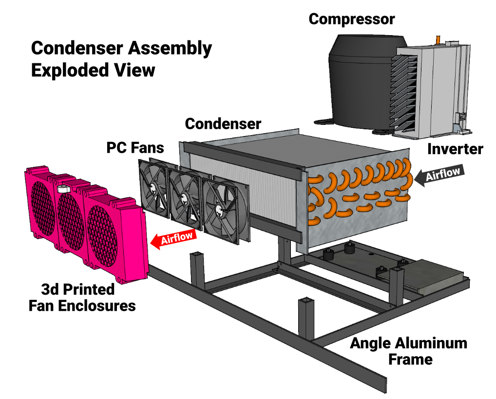
Above is an exploded view of the condenser assembly, with each part labeled. In reality, there were a few more components to this assembly like a 12V power supply to power other electronics, but this gives a good overview of what’s what. The idea was to pull air through the far side of the condenser near the compressor and inverter, and exhaust it out the near side using speed controllable PC fans. This would essentially pull air from below the refrigerator, and exhaust it out the back side.
 Left: Near side of the condenser assembly (fans not mounted). Left: Far side of the assembly.
For the computer fans, I wanted to create an enclosure that would allow for good airflow, while protecting them from our cat who would probably try and break them because she’s horrible. I wasn’t quite sure how hot the air was going to get, so I used PETG filament (Glycol modified Polyethylene Terephthalate, commonly used for soft drink bottles). It has very good strength and higher temperature resistance than the more commonly used PLA filament. Each of the fan enclosures took around 8 hours to print and used around $3 worth of filament material (approximately $25/kg, each part around 120g). They were printed on my Creality Ender-3, which you can find for less than $200 on a good day.
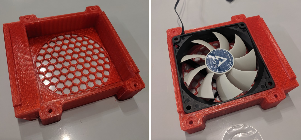 Printing tolerances are good enough with the 3d printer that I was able to securely press-fit the fans into the enclosure.
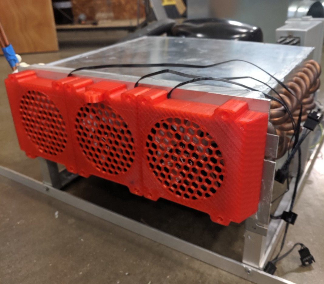 Fans mounted
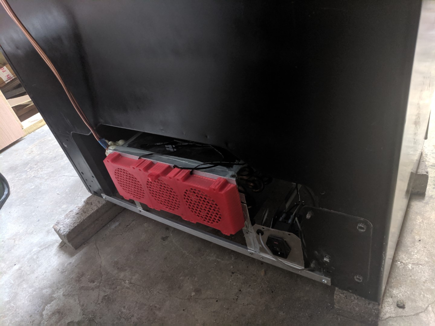 Condenser Assembly installed in the fridge!
Evaporator Assembly

Similar to the condenser assembly, the evaporator assembly is mostly composed of angle aluminum, computer fans, and 3d printed parts. In addition to the fan enclosures, I 3d printed the drain pan. Because of the size of the 3d printer’s bed (8.5” x 8.5” x 8.5”), I needed to print the drain pan in three separate pieces and glue them together.
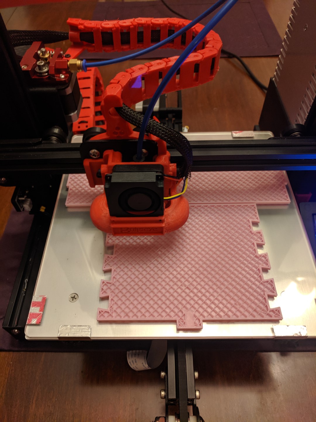 The Ender 3 in action. Yes, I may have made a few modifications…
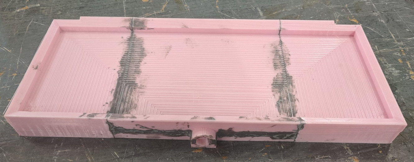 All three pieces glued together with JB Weld. This was also coated with black epoxy spray paint.
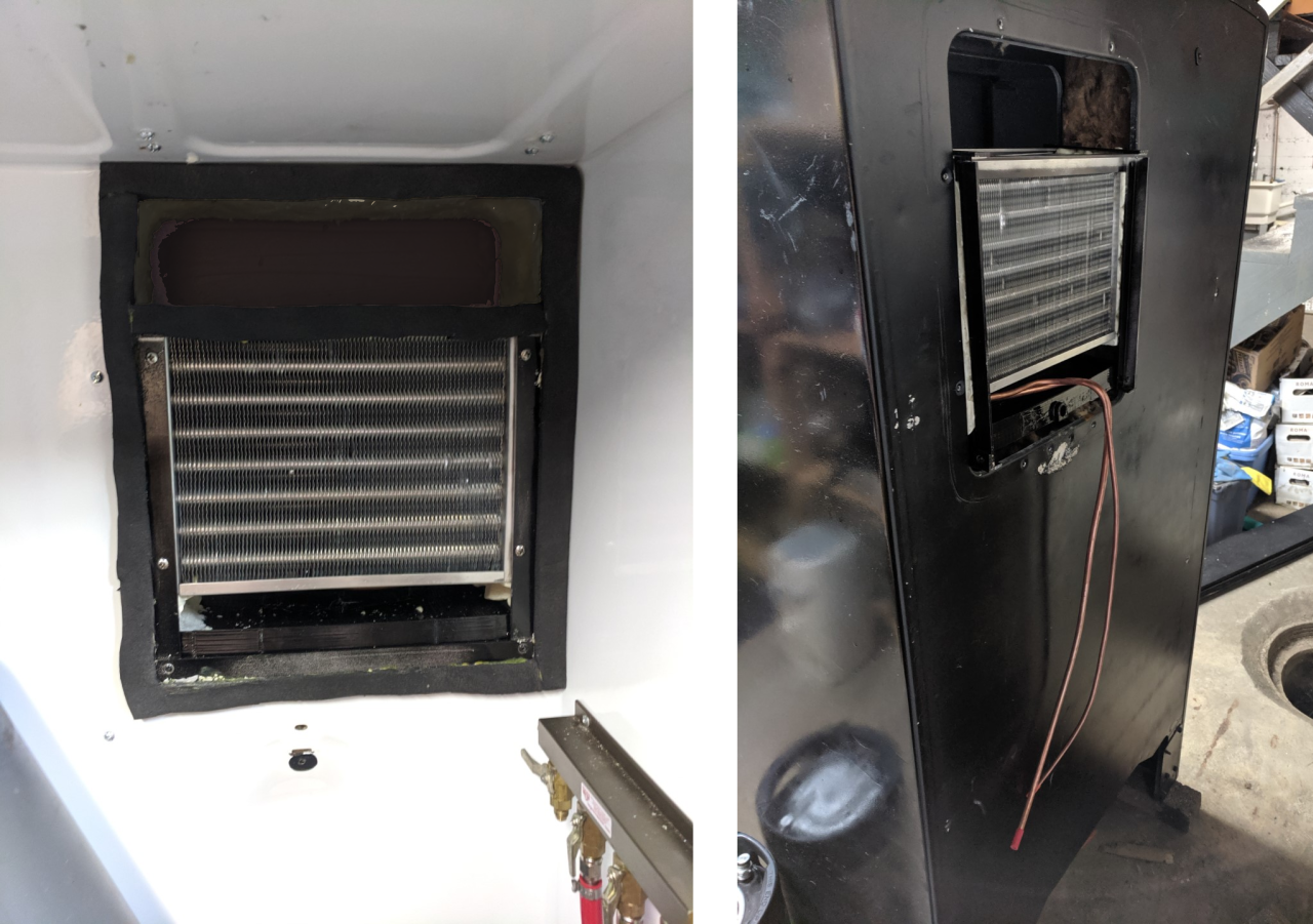 The Evaporator Assembly installed in the fridge. Left: inside the fridge, Right: the back of the fridge.
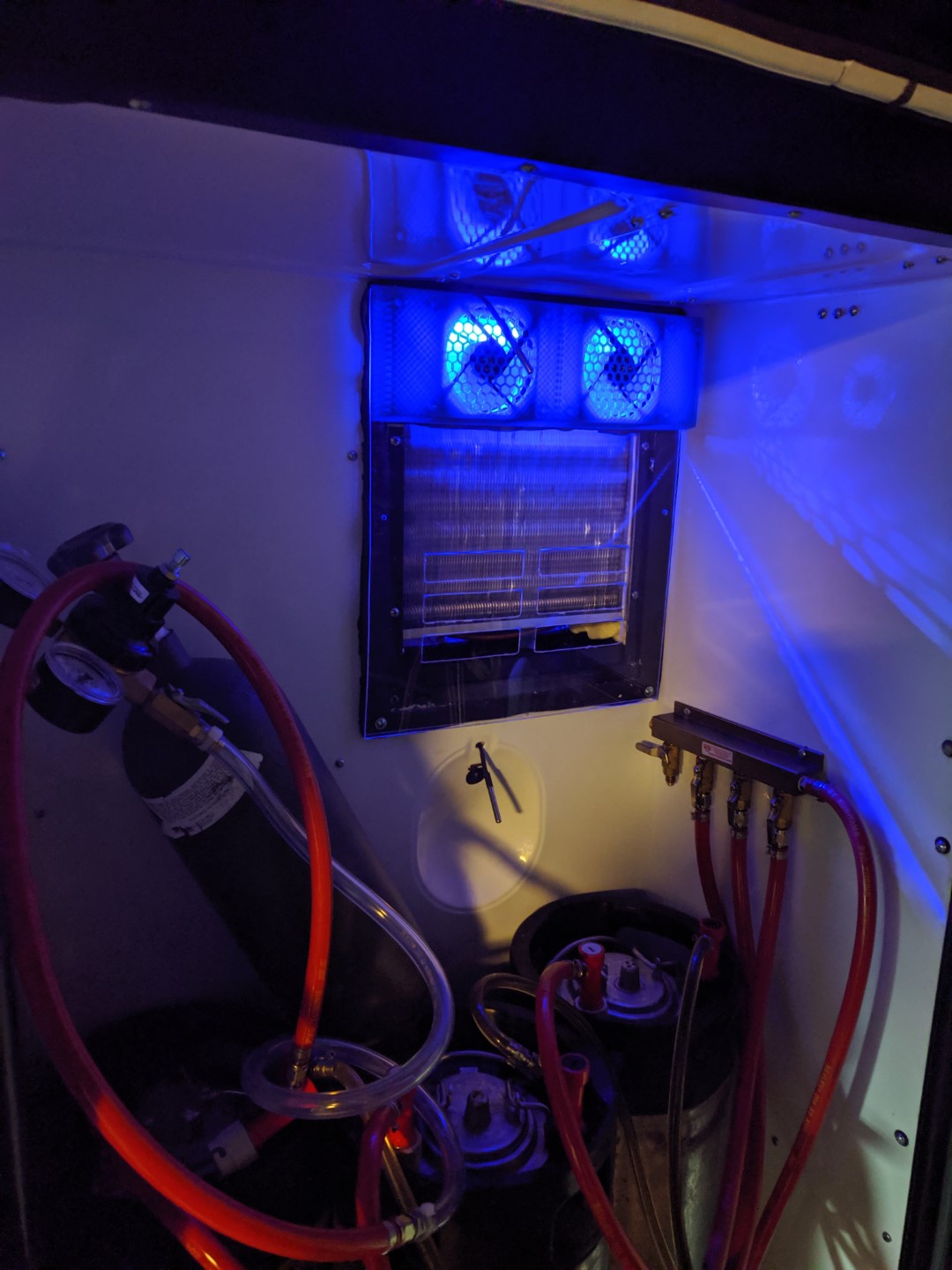 Fans and plexiglass installed. The most critical part of the whole thing is making sure you have bright, obnoxious LEDs.
After the two assemblies were installed, the refrigerant lines were connected up, a vacuum pump was used to remove air and moisture from the heat pump, and then it was charged with R134a. Compared to the old R12 refrigerant, R134a has about 7.5x lower Global Warming Potential and its non-explosive.
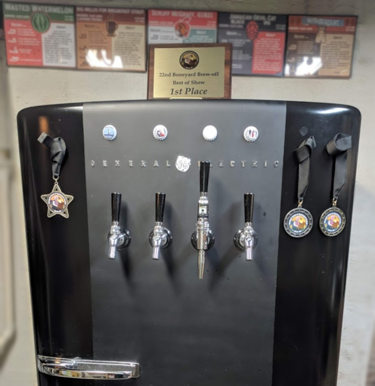
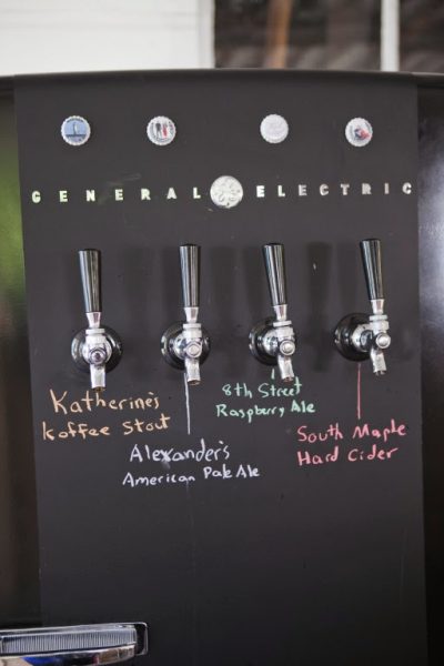
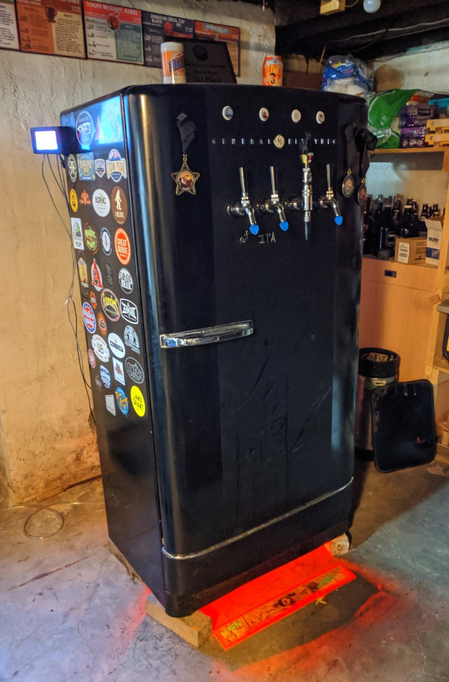 Everything is installed and running! Of course I have red LEDs glowing out the bottom of the kegerator.
Part 6: Smart Ventilation to Smart Refrigeration
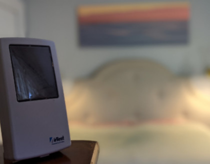
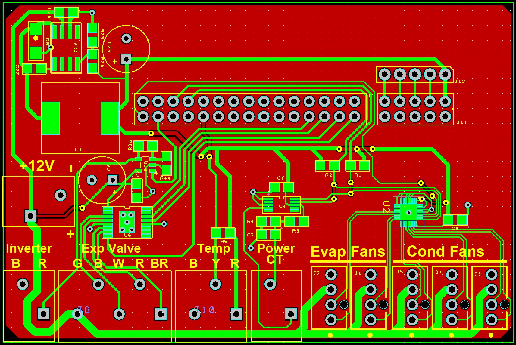
Not only does the kegerator now use the same heat pump components as the CERV, but it also uses the same touchscreen found in the first-generation units! In order to interface with all the components, I needed to make a custom printed circuit board, as seen below. This board plugs into the back of the touchscreen controller.
Power: 12 Volts DC
Inputs:
Outputs:
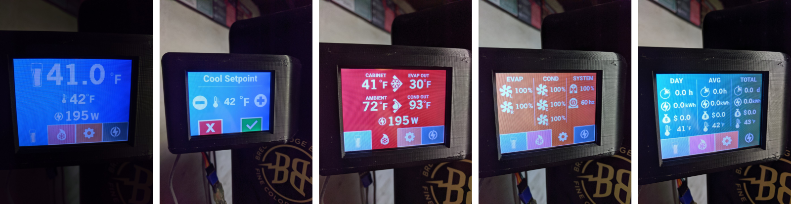
Interface Screens:
Last, but not least: the web-server
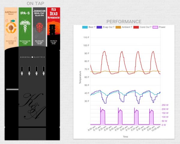 Click here to view the live data from the kegerator! (Note, if you open this on your phone, swipe left/right to switch between the beers on tap and the historical data)
Here’s where I really got to nerd out. I figured that I put so much effort into building the system, I might as well fully commit and make it a web-enabled device. To do this, I used a Raspberry Pi 3A+. For $25, you get a 1.4GHz quad-core processor, 512mb memory, built in WiFi and Bluetooth, and an HDMI output. The great thing about the Raspberry Pi is the number of easy to
follow tutorials and the amount of free, open source software available to the ecosystem. If you’re familiar with Linux systems, you can get up and running in no time. If you’re new to Linux, it’s a fantastic way to learn.
There are basically three parts to the web server. Local communication with the touchscreen display, the database to store historical data, and the actual server that you connect to.
Overview
The touchscreen and Raspberry Pi communicate over a UART (Universal Asynchronous Receiver/Transmitter) port. Basically, this acts as a way for the touchscreen to broadcast its current status to the Pi every 30 seconds. The data packet sent to the Pi looks something like this:
{"T_Amb":72.3,"T_Cout":92.6,"T_Fridge":41.2,"T_Eout":30.0,"Fan_EL":100,"Fan_ER":100,"Fan_CL":100,"Fan_CC":100,"Fan_CR":100,"ExpV":100,"CompHz":60,"Power":195}
If you’re thinking “Hey, that looks like JSON”, you would be right! If your eyes are currently glazed over wondering what I’m on about, the pain will be over soon, I promise.
The Raspberry Pi reads in this packet of data, does some validation checks to make sure all the numbers are within defined ranges that make sense, and then inserts the current data into its MariaDB (MySQL) database.
The main application that handles all of this stuff is written in Node.JS. The application not only listens for the incoming data and stores it in the database, but it handles all of the online server capabilities as well. When you open your browser and visit the app, you’re making a direct connection with the Raspberry Pi and it’s serving up the web app for you to view on your phone or computer. All from a $25 credit card sized device in my basement!
Part 7: The Fun Part…Beer!
What better way to celebrate the completion of the new kegerator than to brew some beer! Check out the brew process below!
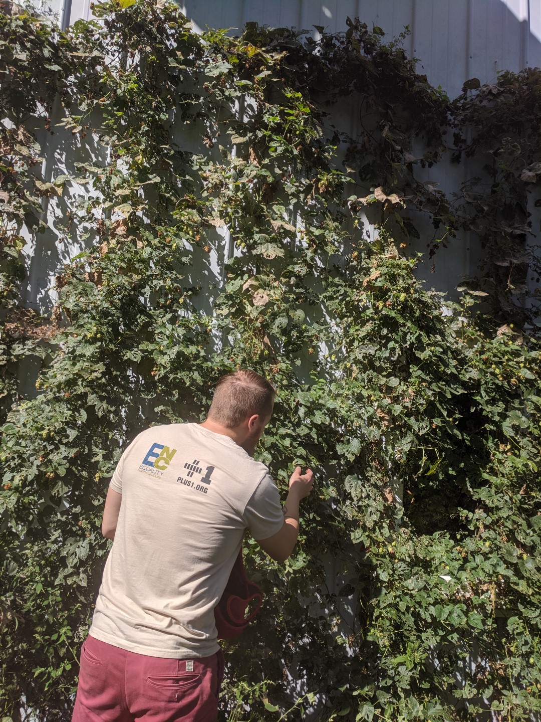 In keeping with using parts from Build Equinox, I used fresh hops picked from the south side of our lab. We think that it’s mostly Centennial hops, but there may be some Cascade mixed in there too.
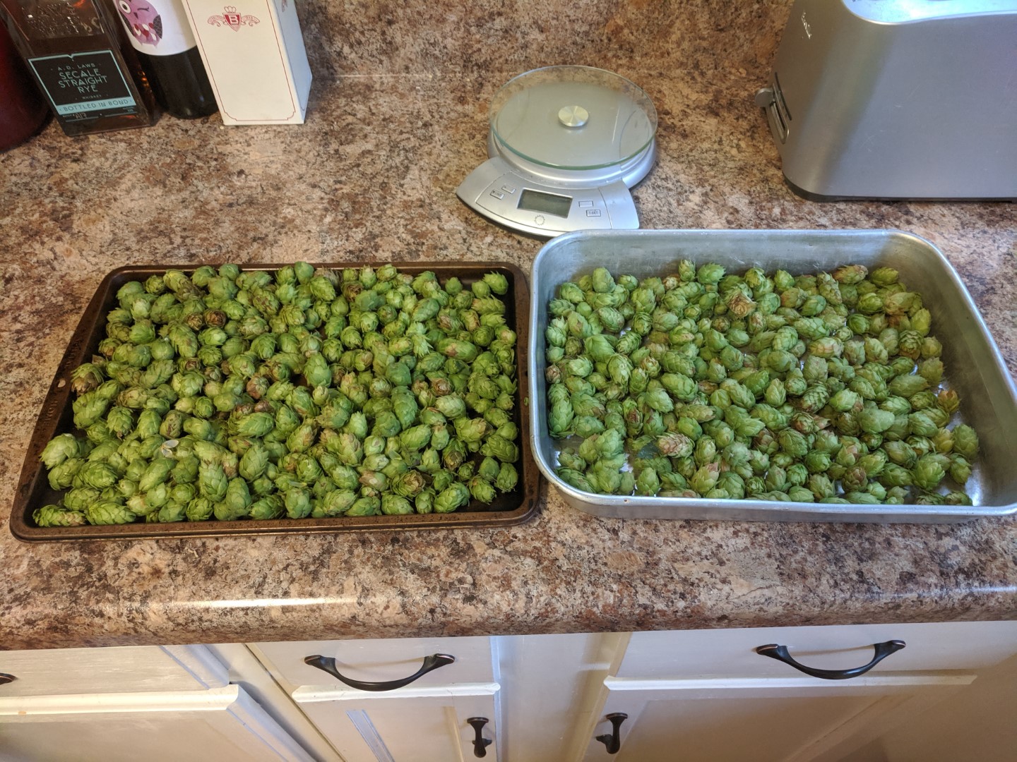 About 6.4oz of hops picked! Since I was going to brew with them right away, I didn’t need to process or dry them.
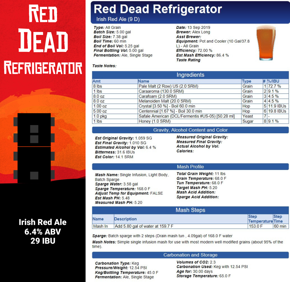 Here’s the recipe for the beer. I decided to do an Irish Red for the first time, and heavily based this off the “Raging Red” Irish Red Ale recipe found on the HomebrewTalk Forums.
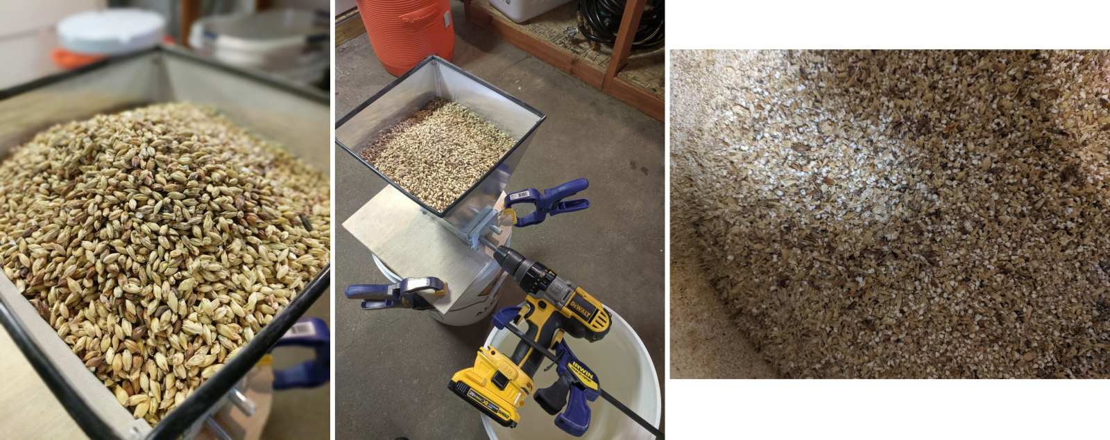 Step 1: Grind your grain. You can usually purchase the grain pre-crushed, but I like to do it the day of to maximize freshness. Also, my number 1 recommended brewing necessity is lots of clamps.
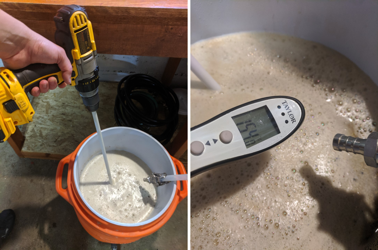 Step 2: the “Mash”. Add hot water to the crushed grains. This is the part of the brewing process where the starches in the grain get converted to fermentable sugars. You generally want to hold the mash temperature at around 153F for an hour (although it can depend on what type of beer you’re doing), so many people will convert a large insulated sports cooler to a “Mash Tun”.
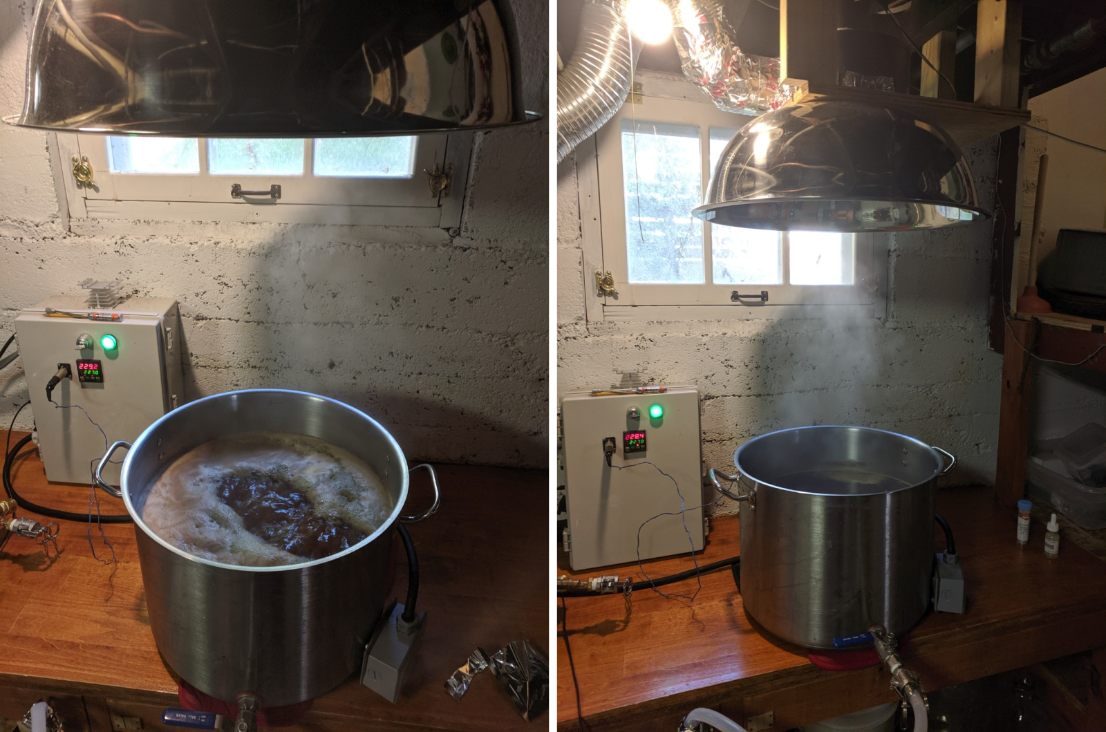 Step 3: After the mash, you drain the liquid back into the brew kettle and start the boil. I built an electric kettle that uses a 240VAC water heater element to control the temperature. Also, since I’m brewing inside, I have a ventilation hood to keep the house from smelling like a brewery. You may notice that my control box does not have a touchscreen interface or web server, so something needs to be done about that…
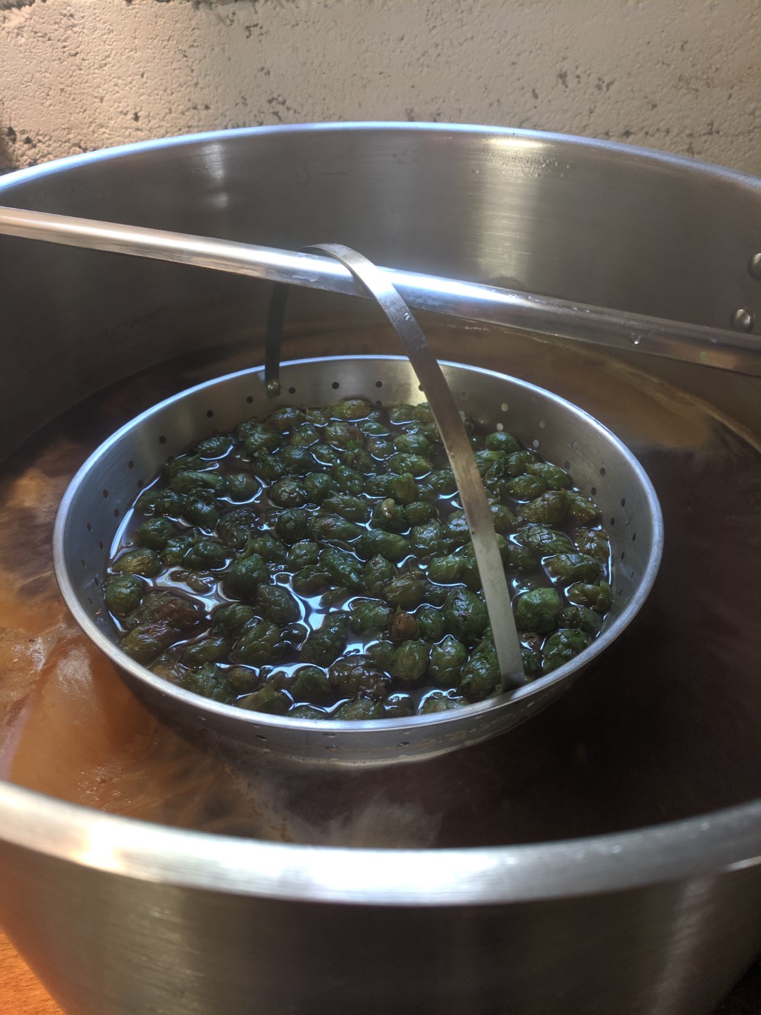 Step 4: Add the hops. Depending on what part of the boil you add the hops, you can add either more bitterness, or more flavor to the beer. For this recipe, the fresh hops were added in the middle of the boil to get a good mixture of both.
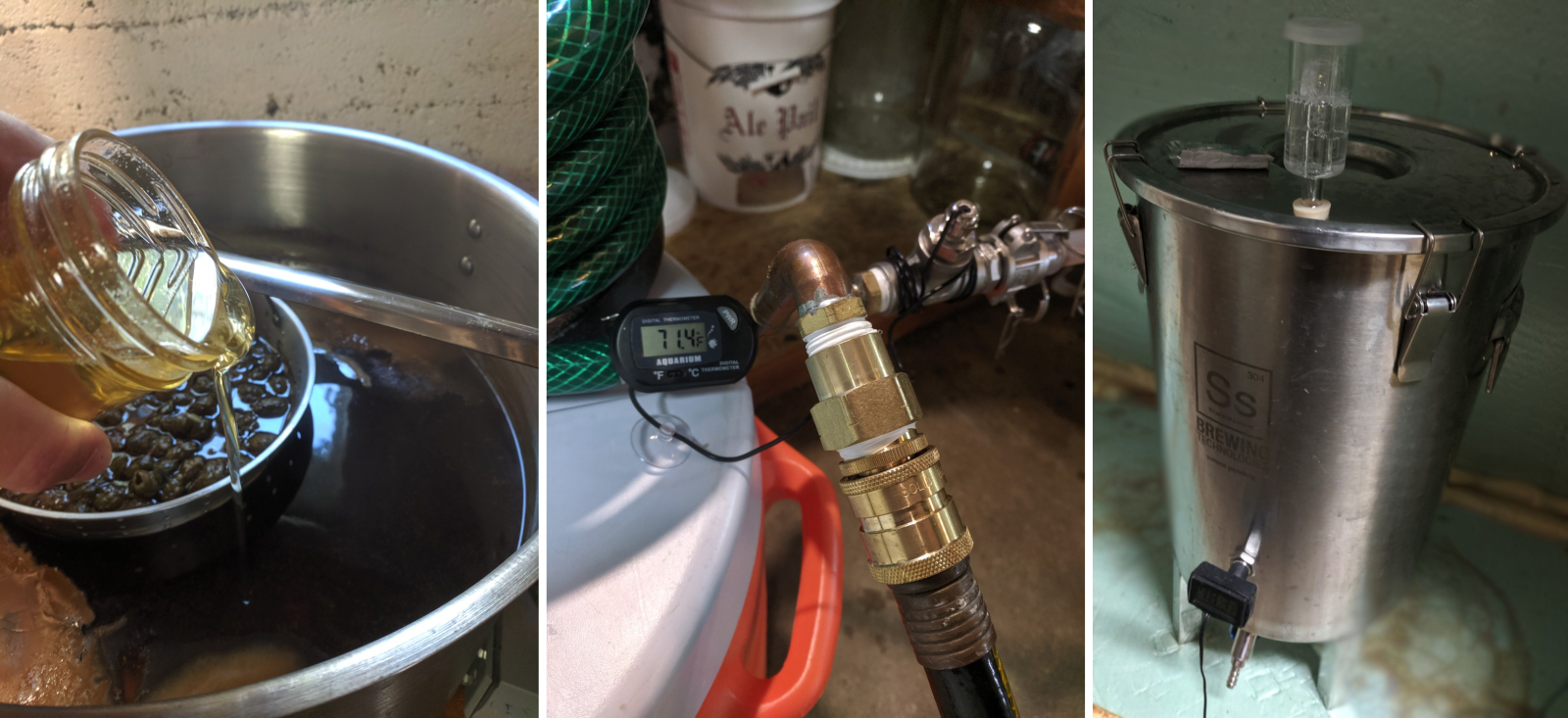 Step 5: After the 1-hour boil was finished, 1lb of local honey is added (left), and then the “Wort” is cooled down to 70-80F (middle). There are a few further small operations, such as oxygenating the wort with an aquarium air pump and “re-hydrating” the yeast to get them prepared for the big game. The yeast is then added to the wort in the fermentation vessel (right). The beer will stay in the fermenter for about 2 weeks, then will be drained into a keg and carbonated. Stay tuned for next month’s newsletter to see the final result!
 Bonus Step 6: Donate the mash spent grain to some hungry chickens.